An electric motor-driven conveyor kept losing its bearings every three months. The maintenance team changed grease, seals, and even shaft alignment, but the failures continued. The real problem appeared only after the design engineer measured the forces acting on the shaft: the radial load at one bearing position was 40 percent higher than the original estimate. Correcting the load calculation immediately pushed the replacement interval beyond two years. That is the practical value of knowing how to calculate bearing loads before you choose a bearing.
Every rolling bearing has a finite fatigue life controlled by the applied load. The basic rating life formula is simple: L10 = (C / P)p, where C is the basic dynamic load rating, P is the equivalent dynamic load, and p is 3 for ball bearings and 10/3 for roller bearings. Because life is inversely proportional to load cubed for ball bearings, even a small error in P has an outsized effect. A 25 percent underestimation of the load can cut the calculated life by roughly half.
Accurate load calculation also drives the choice of bearing type, internal clearance, preload, and lubrication. Loads that are too low lead to premature fatigue and unplanned downtime. Loads that are too high force you to use an oversized bearing with a larger housing, heavier shaft, and higher cost.
Before starting any calculation, recognize the three basic load directions that can act on a bearing.
| Load type | Direction | Typical source | Preferred bearing type |
|---|---|---|---|
| Radial load | Perpendicular to shaft axis | Belt pull, gear mesh force, rotor weight | Deep groove ball, cylindrical roller |
| Axial (thrust) load | Parallel to shaft axis | Helical gear force, propeller thrust, clutch pressure | Thrust ball, angular contact |
| Combined load | Radial and axial simultaneously | Spiral bevel gears, vehicle hubs, crane wheels | Angular contact, spherical roller |
A helical gear, for example, produces a radial force at the pitch circle and an axial force along the shaft. Both components must be included in the bearing load calculation.
Use the following sequence to calculate loads for a shaft supported by two bearings.
For a helical gear with pitch diameter d and torque T, the tangential force is Ft = 2T / d. The radial and axial components depend on the pressure angle and the helix angle; most machine design handbooks give the formulas. A common result is that the axial component from a 20-degree pressure angle helical gear lies between 25 and 50 percent of the tangential force, so it cannot be ignored.
For a belt drive, the shaft force is not just the effective pull. The tight-side and slack-side tensions are added, and that combined force is often much larger than the transmitted torque divided by pulley radius. Always use the belt tensions when calculating bearing reactions.
The calculated nominal load is rarely the real operating load. Shock, vibration, and drive characteristics add extra force. The load coefficient fw scales the nominal load before it enters the life calculation. Typical values are shown below.
| Application condition | Load coefficient fw |
|---|---|
| Electric motors, blowers, lifting platforms, no impact | 1.0-1.2 |
| Gearboxes, compressors, machine tools, moderate shock | 1.2-1.5 |
| Crushers, vibrating screens, heavy impact | 1.5-1.8 |
For belt or chain drives, an additional belt coefficient appears in most bearing catalogues. Gear drives also use a gear coefficient that depends on manufacturing accuracy and meshing impact.
Consider a shaft with a gear force of 5 kN acting at a point 150 mm from the left bearing. The bearing span is 400 mm. The reactions are found with the lever law.
Rleft = 5,000 x 250 / 400 = 3,125 N
Rright = 5,000 x 150 / 400 = 1,875 N
| Bearing | Distance from gear force | Reaction formula | Value |
|---|---|---|---|
| Left bearing | 250 mm | F x 250 / 400 | 3,125 N |
| Right bearing | 150 mm | F x 150 / 400 | 1,875 N |
In a real design, sum all forces on the shaft multiple gear stages, overhung loads, and the weight of the shaft before solving for bearing reactions.
Once the radial and axial reactions are known, combine them into a single equivalent load P. For most rolling bearings, the equivalent dynamic load is:
P = X Fr + Y Fa
where Fr is the radial load, Fa is the axial load, and X and Y are factors from the bearing catalogue. The factor e depends on the contact angle and the ratio Fa / Fr. If Fa is negligible, P reduces to Fr. For a pure thrust bearing, P equals Fa because the bearing is designed to support only axial load.
For slow-turning or statically loaded bearings, use the static equivalent load:
P0 = X0 Fr + Y0 Fa
This value is compared with the basic static load rating C0. If the static load approaches C0, permanent deformation can occur at the contact surfaces.
Manufacturers provide X and Y tables for each bearing type. The values differ between a deep groove ball bearing and an angular contact ball bearing because of the contact angle and internal geometry. A bearing catalogue or an engineering calculator is the fastest way to get these factors without arithmetic mistakes.
The calculated load pattern points directly to a bearing family. Three practical cases appear repeatedly in machine design.
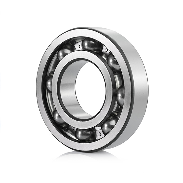
When the axial component is small and the shaft needs a simple, low-cost bearing, a deep groove ball bearing is usually the first choice. It supports radial loads well and a modest axial load in both directions. A common catalog example is the 6311 deep groove ball bearing, used in electric motors and industrial gearboxes.
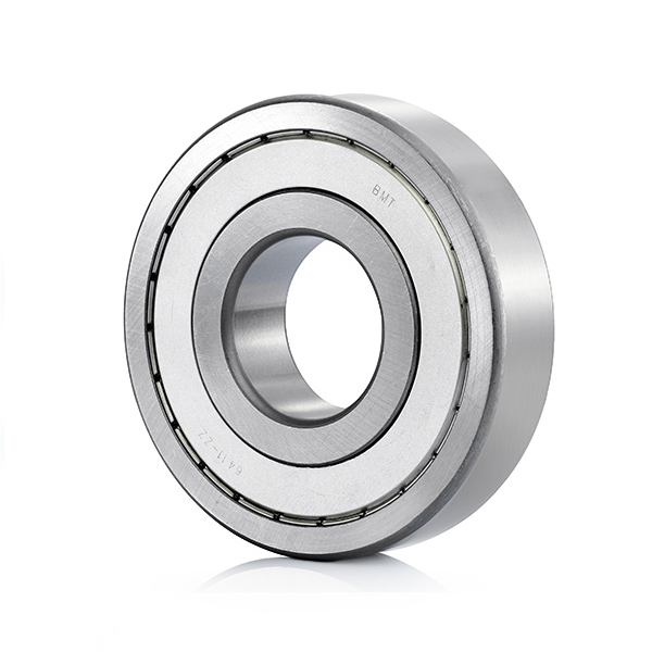 Chrome Steel 6311 Deep Groove Ball BearingThis 6311 deep groove ball bearing supports radial loads and modest axial loads in both directions, making it a common choice for electric motors and industrial gearboxes.View Product →
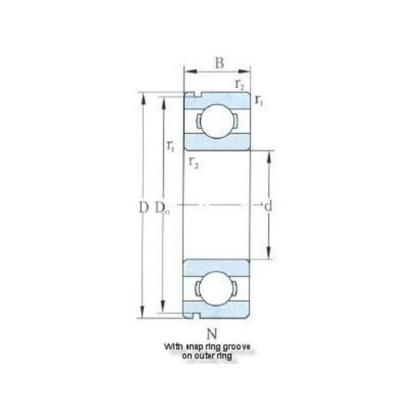
For a higher radial capacity, deep groove ball bearings with snap grooves or filling slots can be used. If you want to compare variants, start with our deep groove ball bearings category.
When a bearing only has to support a shaft collar or a vertical rotor, a single-direction thrust ball bearing is compact and efficient. The load path is parallel to the shaft, and the balls transfer thrust directly between the shaft washer and housing washer. These bearings are not intended for high radial loads and are often paired with a radial bearing in a combined arrangement.
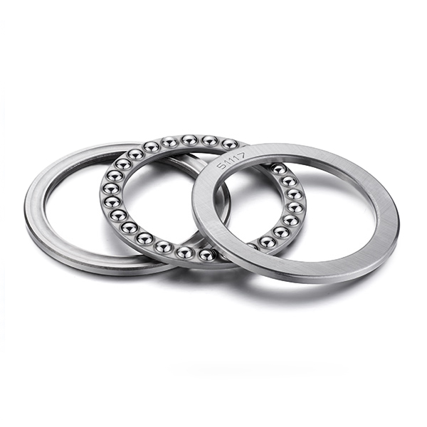 Single Direction Thrust Ball Bearing for Axial LoadsCompact single-direction thrust ball bearing designed to handle axial loads along the shaft, often paired with a radial bearing in combined arrangements for efficient operation.View Product →
To understand the limits of deep groove ball bearings under axial forces, see our article on what axial loads deep groove ball bearings can handle.
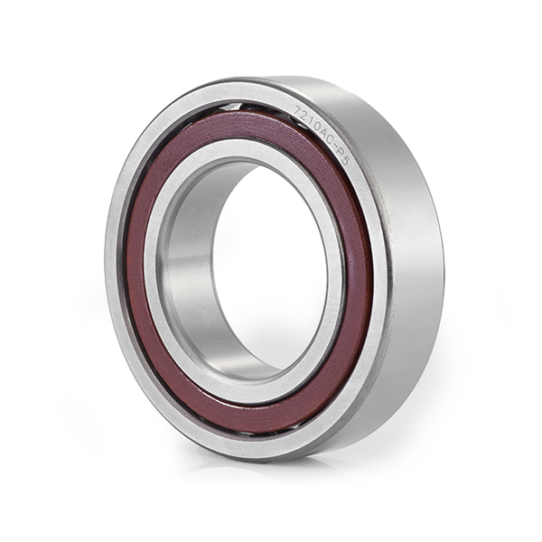
For a shaft that must carry both radial force and a significant axial force in one direction, a single-row angular contact ball bearing is the classic solution. The contact angle creates a larger axial load capacity and provides both radial and axial support in one component.
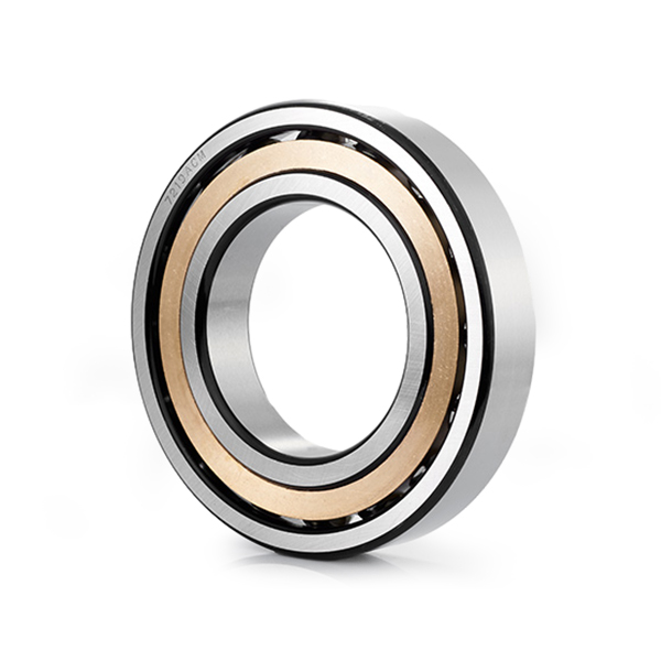 Single Row Angular Contact Ball BearingSingle-row angular contact ball bearing with angled raceways to support combined radial and one-directional axial loads, ideal for electric motors, pumps, and compressors.View Product →
In high-speed applications, two angular contact bearings are often mounted back-to-back or face-to-face to handle axial forces from both directions while maintaining system stiffness.

Copyright © Ningbo Demy (D&M) Bearings Co., Ltd. All Rights Reserved.
 OEM/ODM Industrial Bearing Manufacturers

 Search
 EN
EN English
 Español