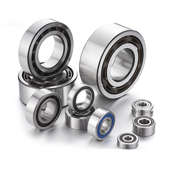
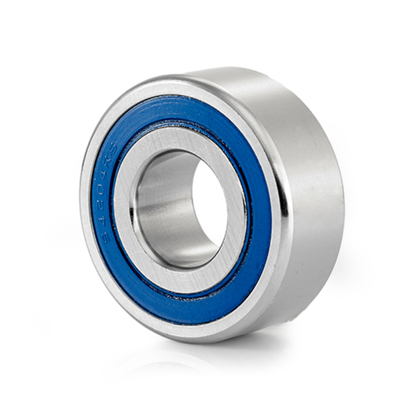
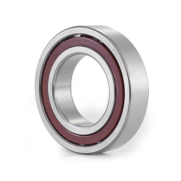
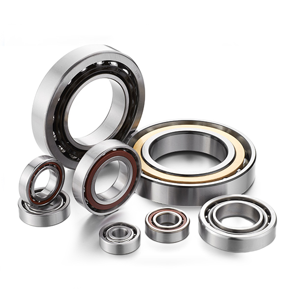
Managing high-velocity rotating machinery requires rolling-element components capable of supporting complex, multi-directional stress vectors. Standard radial ball bearings fail rapidly when subjected to significant axial forces because their straight raceway walls are not engineered to redirect horizontal thrust lines. To solve this fundamental mechanical challenge, angular contact ball bearings feature asymmetrical raceway profiles that safely transfer combined radial and axial loads through a predetermined, angled internal fluid and metal path. This distinct geometry makes them essential components for high-precision, high-stress industrial applications such as CNC machine spindles, centrifugal pumps, automotive transaxles, and aerospace turbochargers.
The defining operational feature of an angular contact ball bearing is the structural design of its inner and outer ring raceways. The inner ring has one high shoulder and one low shoulder, mirrored by the outer ring profile. This intentional asymmetry allows the balls to interface with the raceway walls along a sloped vector rather than straight through the radial plane.
The specific line linking the points of contact between the ball and the raceways is known as the contact angle. This angle runs perpendicular to the rotational axis of the bearing assembly. As a combined force strikes the rotating shaft, the contact angle acts as a mechanical wedge, splitting the force vector into manageable radial and axial components.
Industrial applications rely on specific standardized contact angles, each tailoring the bearing's performance properties to a distinct load environment:
Because a single-row angular contact ball bearing can only support axial forces acting in one direction, mechanical engineers arrange these components in various multi-row configurations. The choice of layout determines the overall rigidity of the shaft assembly and defines how the system handles tilting moments.
The table below provides a detailed structural performance breakdown of the primary mounting configurations used across precision mechanical engineering networks:
| Mounting Configuration Style | Axial Force Direction Capacity | Moment Load (Tilting) Stiffness | Thermal Expansion Sensitivity | Primary Industrial Application |
|---|---|---|---|---|
| Back-to-Back Arrangement (DB) | Bidirectional (Both Directions) | Very High (Wide divergent load lines) | Low (Handles internal temperature deltas well) | Machine tool spindles, conveyor pulleys |
| Face-to-Face Arrangement (DF) | Bidirectional (Both Directions) | Moderate (Narrow convergent load lines) | High (Prone to tightening if shaft overheats) | Agricultural wheel hubs, compressor shafts |
| Tandem Arrangement (DT) | Unidirectional (Single Direction Only) | Low (Requires external counter-bearing) | Moderate | Extruder thrust blocks, heavy oil refining pumps |
| Double-Row Unit Assembly | Bidirectional (Both Directions) | High (Compact pre-assembled unit) | Low-Moderate | Automotive wheel transmissions, blowers |
To achieve extreme positioning accuracy and prevent rotational skidding at high speeds, angular contact ball bearings require the application of a permanent internal axial force known as a preload. Preloading removes any internal radial and axial play, ensuring that each ball remains firmly seated against both raceways at all times.
Without a proper preload, high-velocity operation can cause the balls to slide or spin chaotically rather than rolling smoothly along the contact line. This skidding action shears the thin film of lubricant, generating high heat spikes that lead to localized metal welding, cage fracturing, and sudden bearing failure. Applying a controlled preload—either through precision ground locknuts or calibrated coil springs—strains the elastic contact points slightly. This step locks the balls into a precise path, reducing vibration and ensuring smooth operation.
Designers divide preloads into distinct categories: light, medium, and heavy. A heavy preload significantly increases shaft stiffness, which helps maintain precision under heavy cutting loads. However, a high preload also increases internal friction. As the bearing warms up during use, the inner ring expands faster than the outer ring, which can push internal stresses beyond safe limits. Engineers use precision-ground universal matching bearings to control these forces, ensuring the preload remains stable throughout the entire operating temperature range.
The operational limits and lifespan of an angular contact bearing depend heavily on the materials used for its internal components. Standard bearings use high-carbon chromium steel (such as 100Cr6) hardened through thermal processes to achieve a Rockwell hardness rating exceeding 58 HRC. This provides excellent resistance to subsurface fatigue cracking.
For ultra-high-speed spindles running at speeds above 30,000 RPM, engineers specify hybrid ceramic bearings. These advanced units feature inner and outer rings made of steel combined with rolling elements made of silicon nitride ($Si_3N_4$). Ceramic balls are 60% lighter than steel balls, which drastically reduces centrifugal forces at high speeds. This reduction prevents the balls from sliding outward, significantly lowering internal heat generation and extending grease life up to three times compared to all-steel designs.
The cage or separator that keeps the balls evenly spaced plays a vital role in high-speed applications. While standard pumps use pressed brass or sheet-steel cages, high-speed spindles rely on cages machined from Phenolic Resin or Glass-Fiber Reinforced Polyamide 66. These advanced polymers are lightweight and have a porous structure that absorbs a small amount of oil, providing backup lubrication during sudden high-acceleration phases.
Installing angular contact bearings requires clean workspace conditions and precise execution. Because these bearings are manufactured to microscopic tolerances, slight alignment errors or a lack of cleanliness can cause uneven internal loading and lead to premature failure.
When a high-performance rotating spindle assembly begins to experience accuracy drift or runs hotter than normal, maintenance teams can identify the underlying issue by analyzing vibration frequencies and operating temperatures.
A common problem is a sharp rise in bearing operating temperature shortly after installation. This issue is typically caused by excessive preload tension, which occurs when a technician over-tightens the locknut or fails to account for thermal expansion differences along the shaft line. The high pressure forces the balls deeply into the raceways, cutting through the protective grease film and increasing metal-to-metal friction. To resolve this, technicians must re-measure the assembly clearance, back off the locknut to the proper torque setting, and verify the shaft can expand smoothly through its floating end support.
Another common fault manifests as a distinct high-frequency vibration signal, detectable during routine spectrum analysis. This defect often points to localized ball nicking or raceway flaking, which can happen if fine concrete dust, grinding grit, or coolant fluid bypasses the external labyrinth seals. The abrasive particles scratch the polished surfaces, creating tiny impact pits that degrade rotational balance. To correct this, maintenance teams must replace the damaged bearing cartridge, clean the housing thoroughly, and upgrade to high-density fluoroelastomer (FKM) lip seals to protect the new components from future contamination.

Copyright © Ningbo Demy (D&M) Bearings Co., Ltd. All Rights Reserved.
 OEM/ODM Industrial Bearing Manufacturers

 Search
 EN
EN English
 Español